Root node
Initial protocol by Antycip
The rendering system configuration is complex, but an original, projection-compliant version will be provided to you by InMind-VR and Antycip.
What is the root node
The camera system of a Cave protocol can be extremely complex, much more so than the simple system of conventional or VR protocols. In order to accommodate all projection configurations, MindDev Sim provides a specific node natively integrated into the virtual camera system.
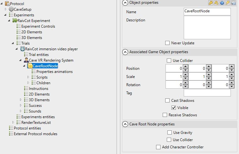
The root node, named "Cave Root Node" by default, is the origin node of the entire virtual representation of the physical projection system. This node, integrated in the camera system of any Cave-compatible trial, contains a structure describing all the physical screens, tracking and interaction systems.
We have described, in the configuration, all the computers that make up the rendering cluster, as well as the display windows. These windows have a linked camera name parameter. The CaveRootNode is the place, in the test structure, that should contain the rendering camera information.
RootNode repository.
We need to describe the physical configuration of the projection system virtually, so we need to define a coordinate system that allows this virtual description. The origin of this reference frame must be as logical as possible to allow the simplest possible expression of coordinates. Until now we have been talking about projection systems and computers, we must now take into account the screens, the supports for image projection.
Physical position and virtual position
The origin of this reference frame will be equivalent to the position of the root node. When a physical object moves closer to the center of the physical reference frame, it will be virtually very close to the root node in virtual space.
The description of the projection system therefore involves expressing the positions, orientations and sizes of each screen that make up the display system. The choice of the reference frame is specific to each immersive space, however, it must be as logical as possible and allow the expression of the information on the screens as simply as possible.
Very often, this reference frame will correspond to the reference frame of the tracking system: by choosing to make the two reference frames correspond, there will be no transformation of coordinates to produce when receiving the tracking information.
Origin of the reference frame
Make sure you have a simple and remarkable reference frame origin in your physical space. The easiest way is often to put it on the ground, in the center of the projection space, so the screens will have a height position equal to half the screen height.
Orientation of the frame of reference
Make sure you logically orient your referential in relation to your screens. In a rectangular or square room, with 90° corners, the axes should be aligned with the axes of the screens, so the screens will have some positional components in common with each other and the orientations will be 0°, 90° or -90°.
Root Node Position
The root node must remain at position {0,0,0} and rotation {0,0,0}.
Screen description
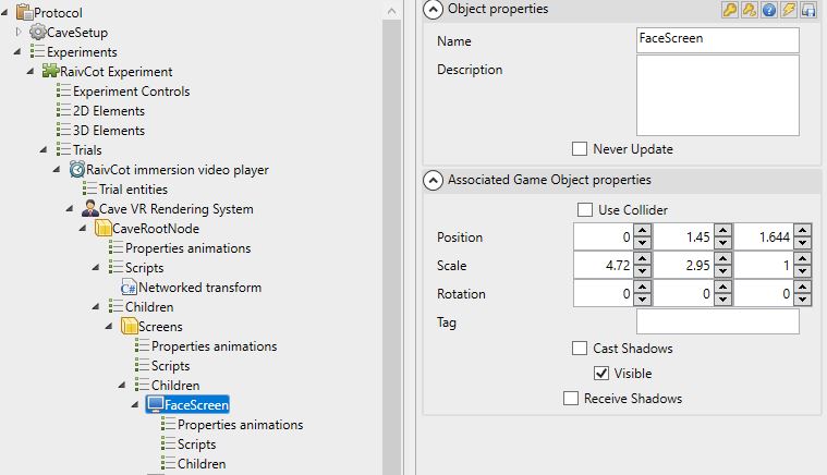
The screen entity is used to create a virtual screen that corresponds to a real projection screen. Expressed in the physical reference frame, it should be given its position, size and orientation. In this regard, the choice of the coordinate expression frame of reference is crucial on the complexity of the values to be filled in.
Expression units
Position and size are expressed in meters.
Beware of the orientation
The orientation of a virtual screen must match the orientation of the physical screen expressed in the chosen frame of reference.
Description of a camera
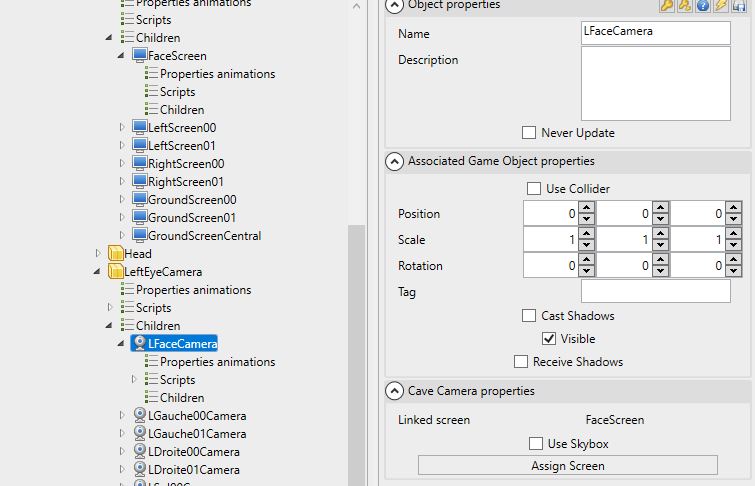
Much simpler, a virtual camera represents a viewpoint in space. A virtual camera is linked to a screen. For each screen, there is at least one camera and in case of stereoscopy, two cameras will be needed, one for each eye.
Camera-Screen link
The property panel of a camera allows you to select the screen it is linked to.
Camera orientation
In a very simple way, the orientation of the camera must match the orientation of the screen it is linked to.
Point of view ?
A camera represents a point of view. By linking it to a screen, MindDev is able to calculate the image to be projected corresponding to the position of the camera in space with respect to this screen.
Participant's point of view ?
The usefulness of a projection room lies in the ability to match the images to be displayed to the view of the real participant. Virtual cameras are naturally intended to receive information about the position and orientation of the participant's head in order to calculate the right point of view at any given moment!
Night vision system
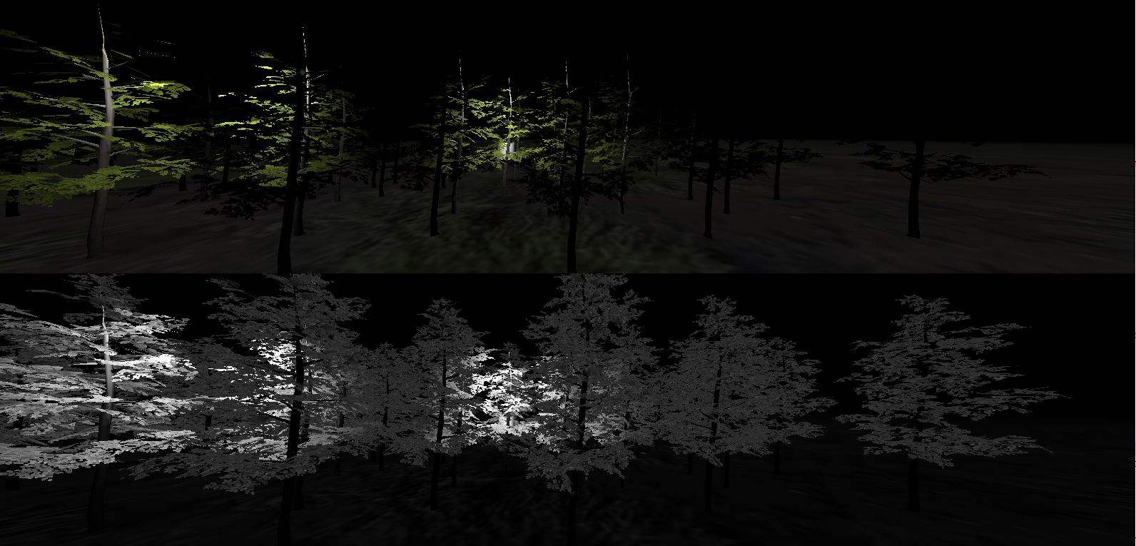 MindDev offers a night vision system in the form of a camera behavior (script). This system proposes a black and white rendering and manages the light emission via the emissivity properties of each material of the scene. This camera effect is not visible when editing the protocol.
Interaction and pointing system, tracking
MindDev Sim relies on the VRPN protocol for tracking real objects (head, hand etc.) and interacting with the virtual world via ART Flystick or Vicon Apex type devices. A documentation section is available here.