The behavior graph system
The Behavioral Graph System offers the ability to create your own behaviors with complete control. It is indeed possible to simply program complex behaviors by combining different blocks (called nodes to differentiate them from MindDev nodes) with each other.
Behavior graph
The behavior graph system allows a non-programmer user to develop their own behaviors.
How it works
In a behavioral graph, each node has its own functionality and produces only one action. Depending on the parameters provided to it, the node will produce an action and possibly output values in the form of output parameters.
The combination of nodes allows the output parameters of one node to be used as input parameters for another node. It is therefore possible to create behaviors that change depending on the state of the input values.
A behavior graph is deterministic, and the order in which the nodes are linked is very important. Indeed, for a given node to work correctly, all its parameters must be updated before executing its action. Moreover, it is possible to link an output parameter to several input parameters (except the parameter controlling the execution flow), but it is not possible to link several output parameters to one input parameter.
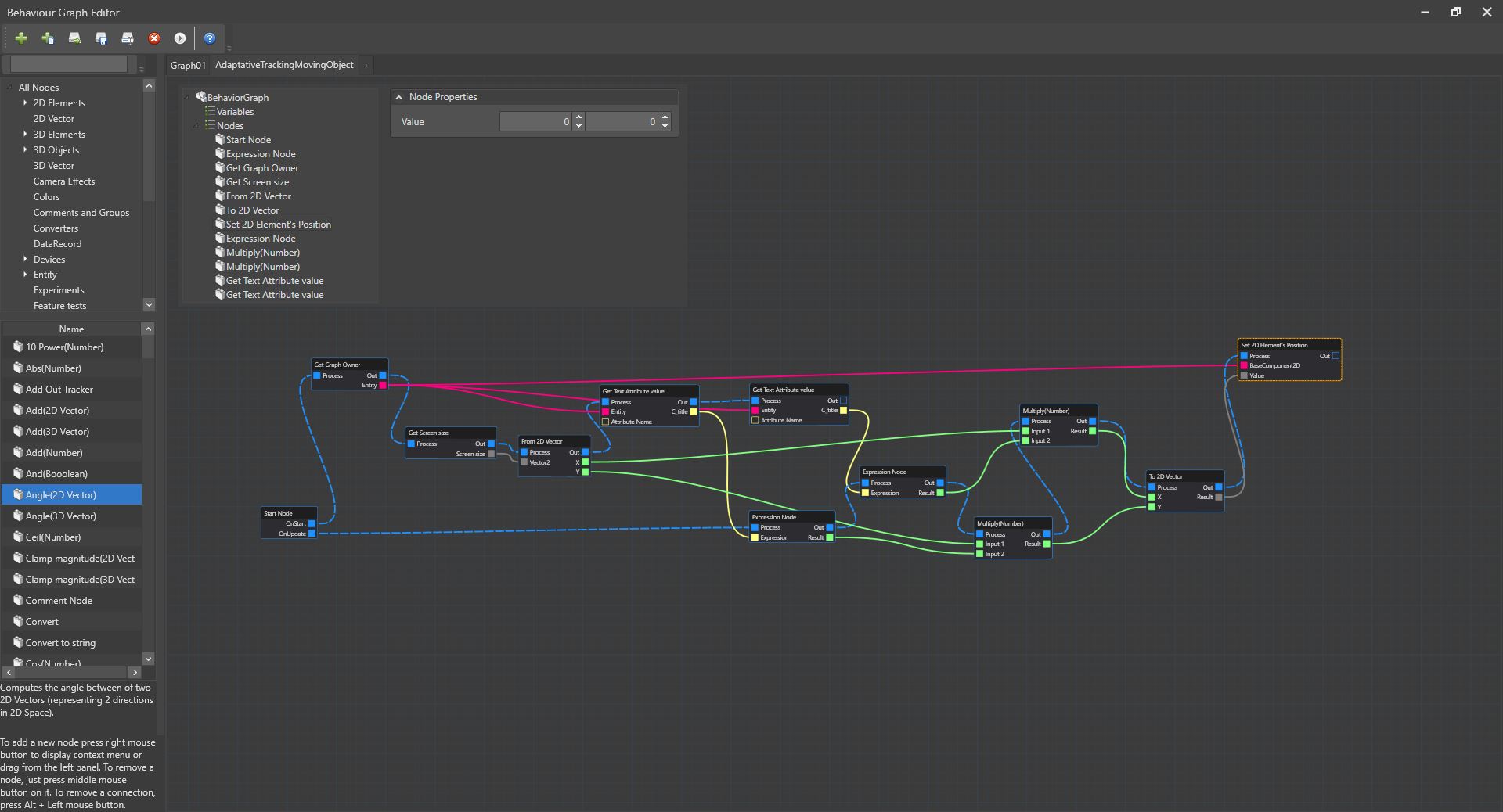
Graphical interface presentation
Launching the graphical interface
The editing GUI can be launched from the general MindDev menu (Windows/Behavior Graph), through the main toolbar, or via the attributes and behavior panel of compatible entities.
The graphical interface offers all the commands to manage your graphs, create and modify them. For this purpose, a toolbar allows the quick management of files and the creation of new types of graphs (generic graph or data filter graph).
The left banner displays all the available nodes. All nodes are categorized and have a short help indicating their action. A simple drag and drop of a node allows you to add it to the graph you are editing.
A text field in the lower part indicates how to manipulate the window:
| Action | Consequence |
|---|---|
| Mouse Wheel | Zoom In/Out |
| Drag and drop with middle mouse button | Lateral move |
| Drag and drop with right mouse button | Lateral move |
| Drag and drop with left mouse button | Multiple selection |
| Left mouse button on a node | Node selection |
| Left mouse button on an empty area | Unselect selected node |
| Middle mouse button on a node | Delete node and its connections |
| Alt+left mouse button on a connector | Delete all connections of the connector |
| Drag and drop with the left mouse button from a connector to another connector | Create (if compatible) a connection |
The editing area, which occupies a large part of the space, allows you to design your graphs and gives access to the parameters of the selected node. It is thus possible to add new nodes (by displaying the contextual menu) but also to create graph variables.
The node
A node is an elementary brick in a more complex whole that is the graph. A node has its own logic. It possibly has input parameters (represented as connectors and also non-connectable properties) and output parameters (represented as connectors).
In case the node is configurable, the configuration is done in the popup window of the node settings.
configuration.
Running a node
When executing a node, the node will take the input values and execute its logic. When this logic is complete, the node will update the output parameters always ending with the execution flow, so we are assured that the next nodes executed will have the latest input parameter values.
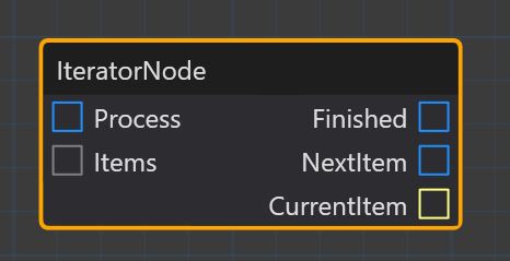
The connector
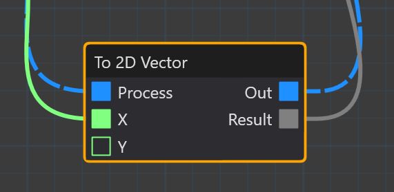
Each node has its own input and output connectors. These connectors are strongly typed (they have different colors, so you can tell their type). A connector can only be connected to another compatible connector.
Any connector.
There is a type of connector, the "Any" connector that is compatible with any other type of connector. However, this connector is rare and is only available in a few nodes.
Connector converter?
It is not possible to change the connector type of a node. However, it is possible to convert a parameter type into another type, this is especially the case with the IObject - ITrackable conversion and the conversion of any connector into a string connector. Conversion nodes are available in the "Converters" category.
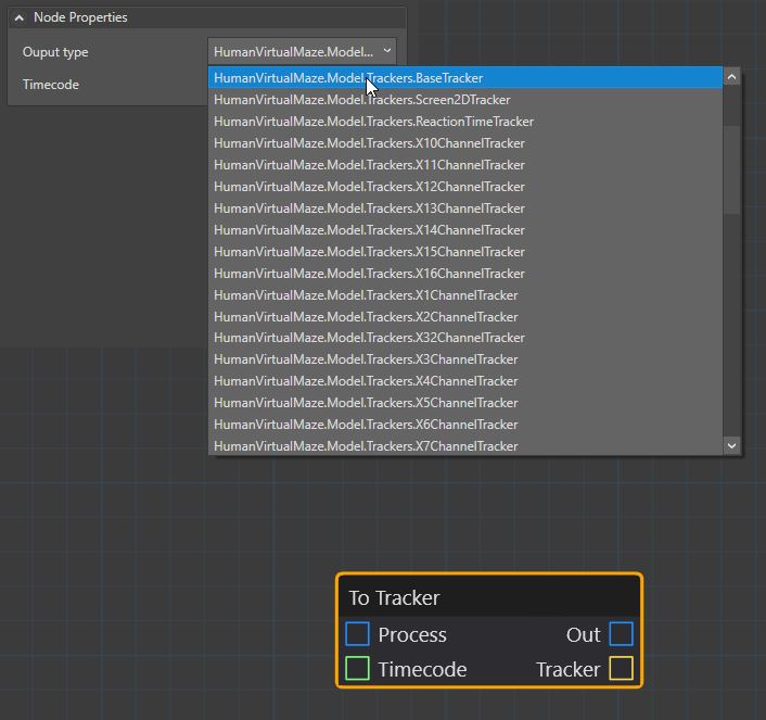
Modification of connectors
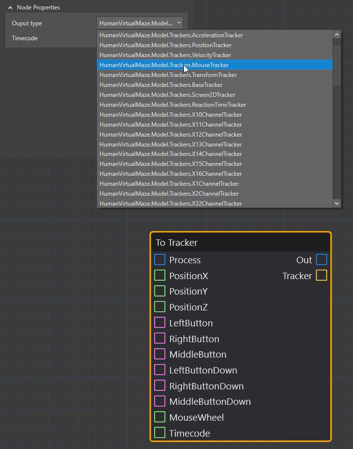
Some nodes have specific internal parameters (which are not connectors) that have a direct influence on input or output connectors. For example, there are two nodes for creating data trackers that allow you to choose the type of tracker to create. When the type is chosen, the input and output parameters are updated.
Connector Not Connected
When adding a node, connectors are not connected to other nodes by default. It is advisable to create your own connections according to the desired actions. It is quite possible that some of the input connectors of a node remain unconnected. In this case, it is possible to configure (on certain types of connectors only) the default value to be used.
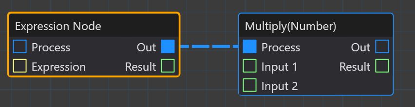
Representation of a connector
A connected connector has its color cartridge filled, whereas if it is not connected, its color cartridge is empty.
The connection
There are two types of connections possible in the graph editor. Both essential, these connections have different behaviors. The first, the process connection allows you to manipulate the order of activation of nodes. A given node will only be executed after the node to which its input is connected is executed. This provides a deterministic flow, and does not allow multiple execution.
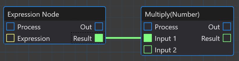
The second type of connection allows the connection of all other parameters (other than the execution stream) for all other connector types.
Deleting a connection
Deleting a connection is possible by left-clicking the mouse and holding Alt on the connector.
Specific nodes
There are two nodes that are a little different from the others because of their configuration
Start nodes
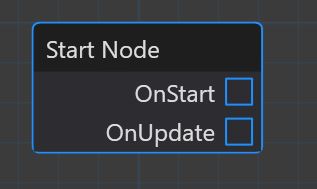
So far we have described nodes as necessarily having an input and output execution flow. Start nodes differ in that they do not have an input execution stream. These are recognized by MindDev as execution start nodes and are activated automatically.
Only one start node
For a given graph, there can only be one start node. Without a starting node, the graph will produce nothing.
It is possible to capture the event of click on a 2D button, as well as the mouse hover on them. It is thus possible to create behaviors during mouse clicks, which will therefore not be updated at each frame, but only on event.
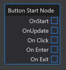
Adding a click management node
The graph will check for the existence of a start node when adding a click management node. It is not possible to have two start nodes in a graph, so the initial start node must be deleted in order to add a different one.
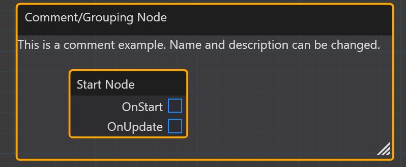
The comment node
The comment node is special because it has no parameters. It is only possible to add text to it. This comment node is also a grouping node, so when a conventional node is inside the comment node it is moved along with the comment node if the latter is moved.